
RHEOX INSTALL GUIDE
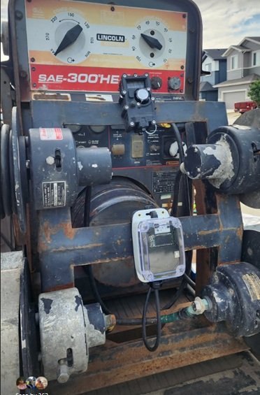
On July 9, I installed a Rheox to a SAE300-HE machine which had a L21-20R receptacle. The key consideration is that the receptacle is a third party installed item and our job is to map it out. The Rheox is a polarity dependent unit. That means you can’t mix up the positive and negative lead.
Our job is to understand the pinout which most likely consists of two AC wires, a ground, and two DC wires. With a multimeter, we are going to find the two AC wires that we use for grinding in order to exclude them from our search.
We will probe the pins of the receptacle. If your multimeter cannot reach inside the receptacle, use an existing plug with the back off and put your probes on the screws. Important you understand what I’ve written below is to be done exactly to achieve accuracy and minimize the steps.
Steps Are:
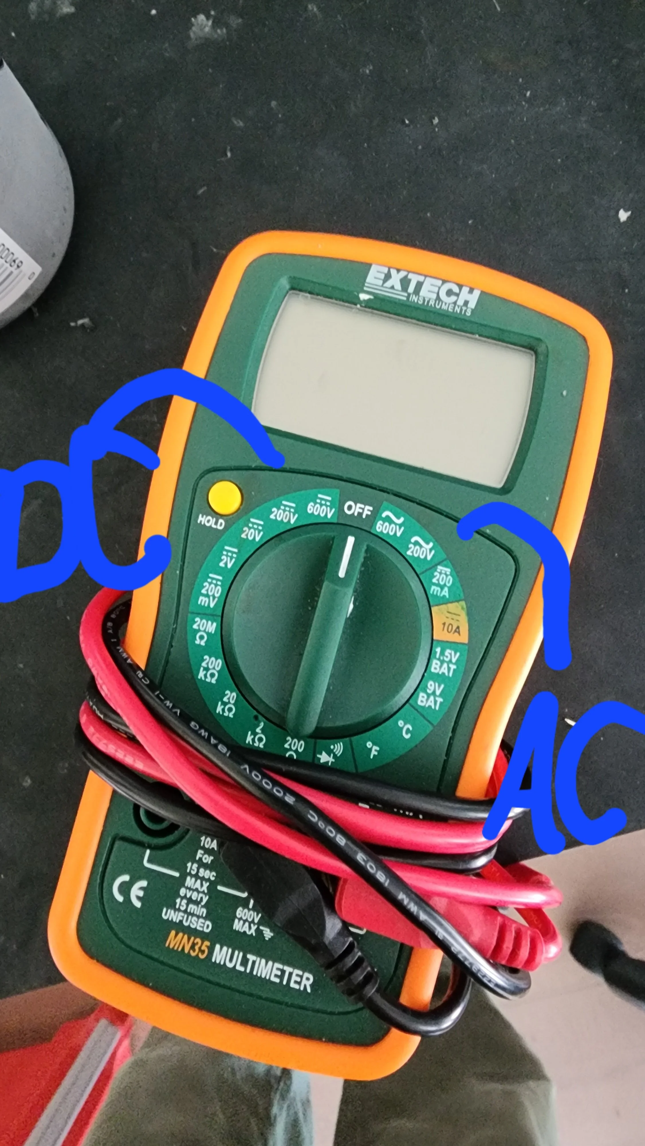
Machine running, remote switch set to local, put your multimeter to 200 AC, and find two spots that provide you something like 80VAC in low idle and 120VAC in high idle. In my install, it was W and X.
Now that W and X were excluded, I have Z and Y left over (I assumed during my install that the center pin was ground)
Machine running, remote switch set to remote, put your multimeter to 200 in the DC mode. I put my leads on Z and Y and swapped them until my reading was positive and not negative. Once positive, I wrote down the letter that the red lead was attached to. In this case, it was Z positive and Y negative.
Now that we have Z positive and Y negative, with your leads on those two, reach over, machine running, and set your remote switch to local. Done correctly, your value will go away.
5. Done right was a confirmation step that Z is positive and Y is negative. The Rheox has two 14 gauge wires, one red and one black. The red is the positive lead. The black is the negative lead. They are polarity dependent and cannot be reversed.
Next step is the flyback diode install: https://www.dkwremotes.com/blog/flybacksimple
BATTERY FIX FOR THE G1 HAND REMOTE
Ok, so listen. The first time I heard of a customer having the hand remote turn on only when plugged in, (charge light flickering), when he came to show me, it was working so opportunity lost. The second one, I serviced and bent back the battery clips which were so bent out, I assumed customs during shipping did it and did not clue in yet. Now, today, this customer lived 40 minutes away from my house, so this was my opportunity.
I packed up everything I needed with enough understanding what was happening. All third party remote makers hard solder to the battery ends. I do. Just not the G1, until now. I flowed out two solder joints, reassembled the hand remote and it is good. It was a field fix so I didn’t need to drive back. The rest will be under microscope.
Now in retrospect, what should have happen is I should have bonded the battery to the board which would stop it from vibrating and pushing out the battery clip a sixty fourth or greater. We are past that and will hard connect it like the evoR’s
What does that mean for you. Any hand remote assembled or serviced after May 19, 2026, will be good to go. Any hand remote assembled before this date, will be serviced by me. We will come together, and arrange shipment when it suits your schedule.
In the meanwhile, I would suggest you always have your charge cord and charge plug on hand as the hand remote will work fine without the battery.
Again, what is the symptom, when plugged in, the charge light flickers and if you have the hand remote turned on, and then you unplug the charge cord, the hand remote turns off.
We will get it fixed. I’m relieved to find out a correct fix.
The All New Ghost Series Wireless Remotes (Release Date: Q1 of 2026)
DKW Remotes is excited to announce the introduction of our all-new Ghost line of Wireless Remote Sets starting with the G1 model in 2026. After six years of development of the EvoX/R line, we are prepared to make not a step but a leap forward in remote technology.
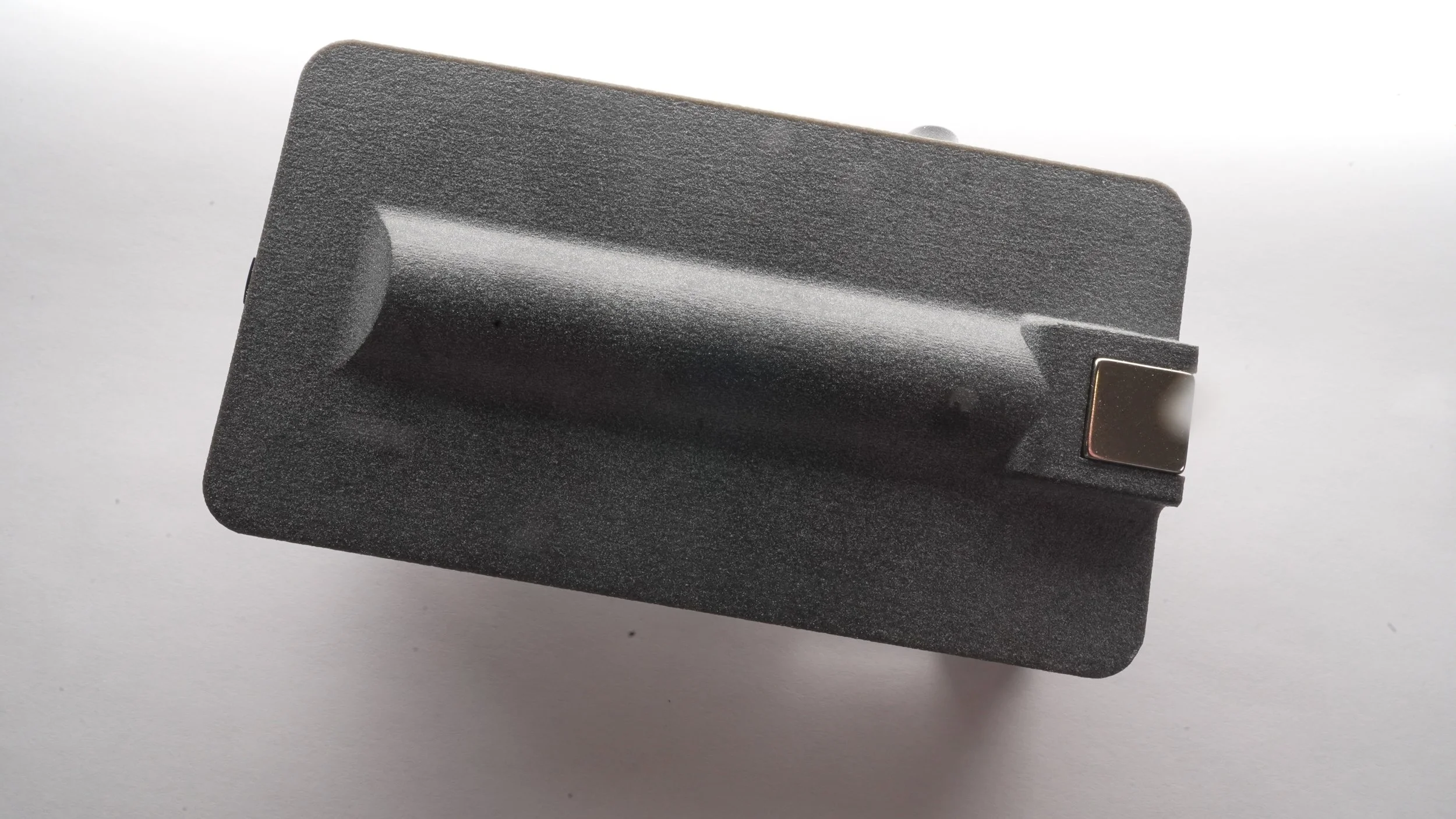
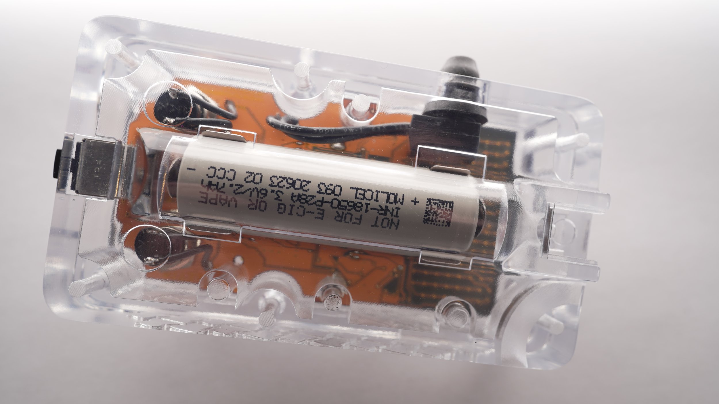
Coming in at 218 grams which is about half a pound, the G1 hand remote starts off with every innovation and trick we have learned since 2016. And, a few new ones. The main redeeming factor is a flashable firmware by the end user. But, more on that later.
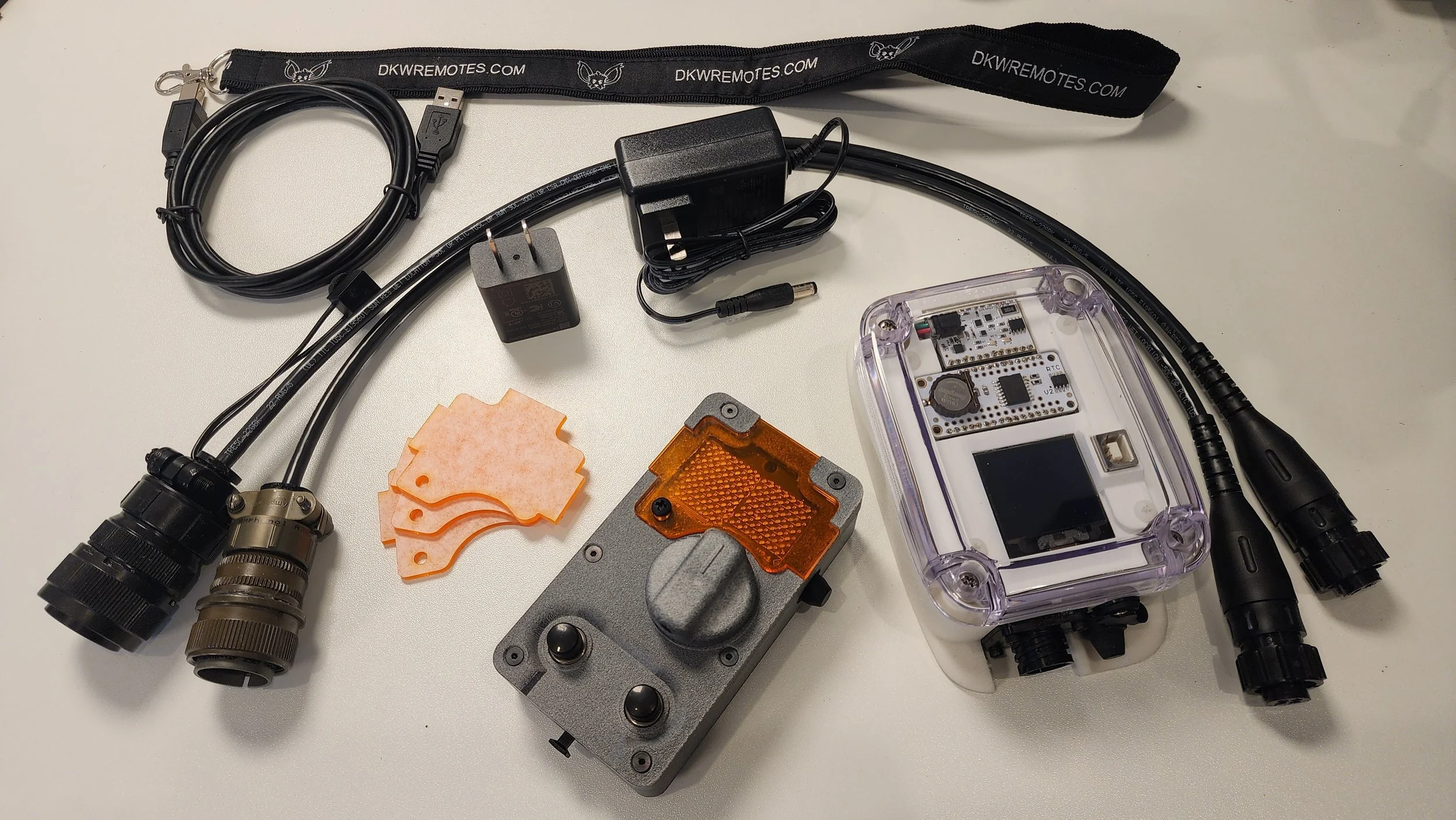
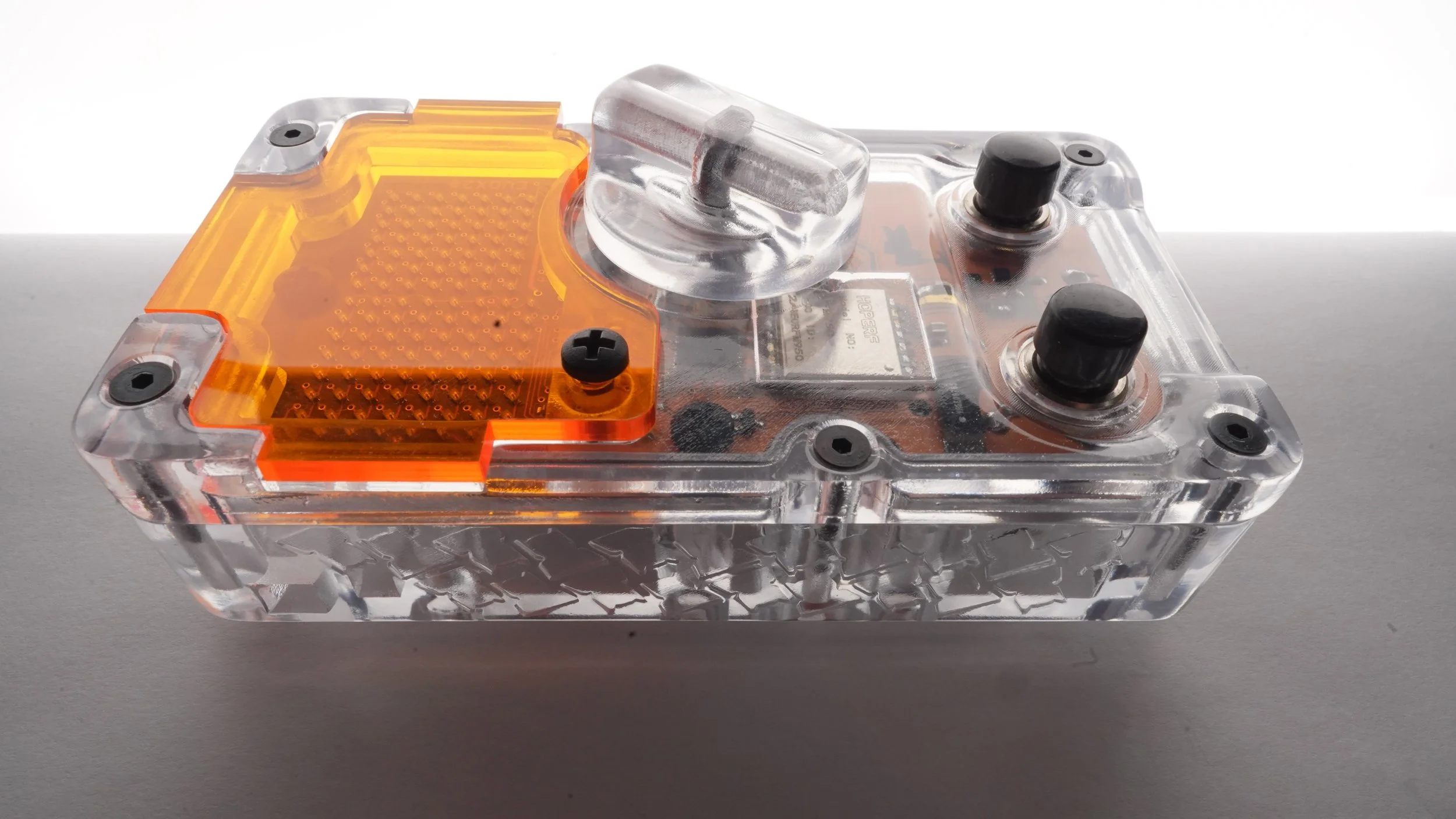
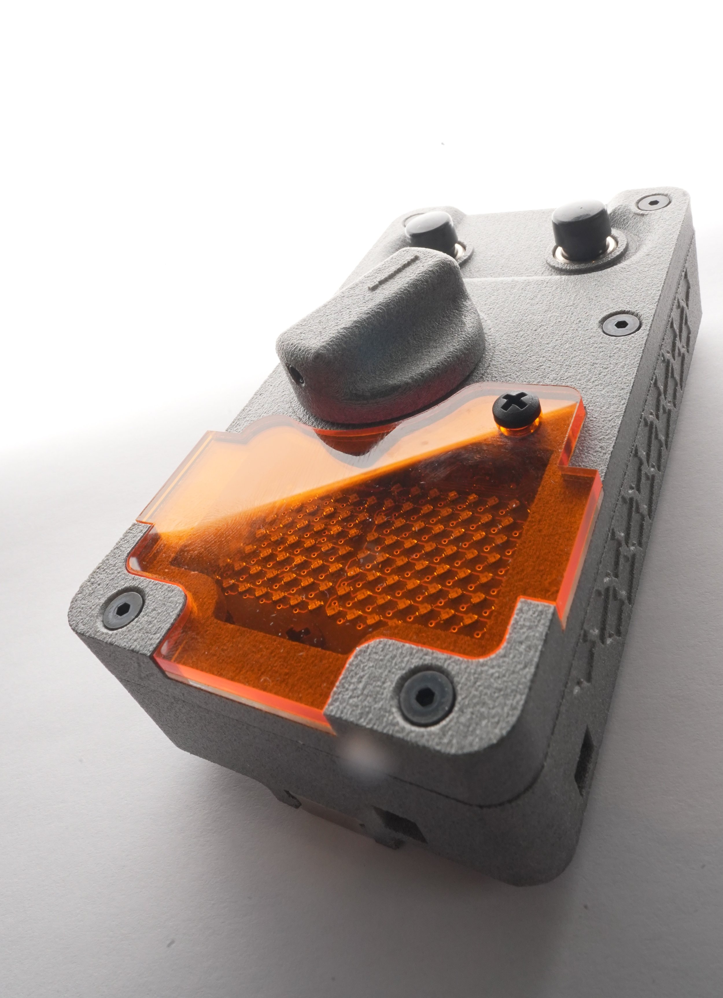
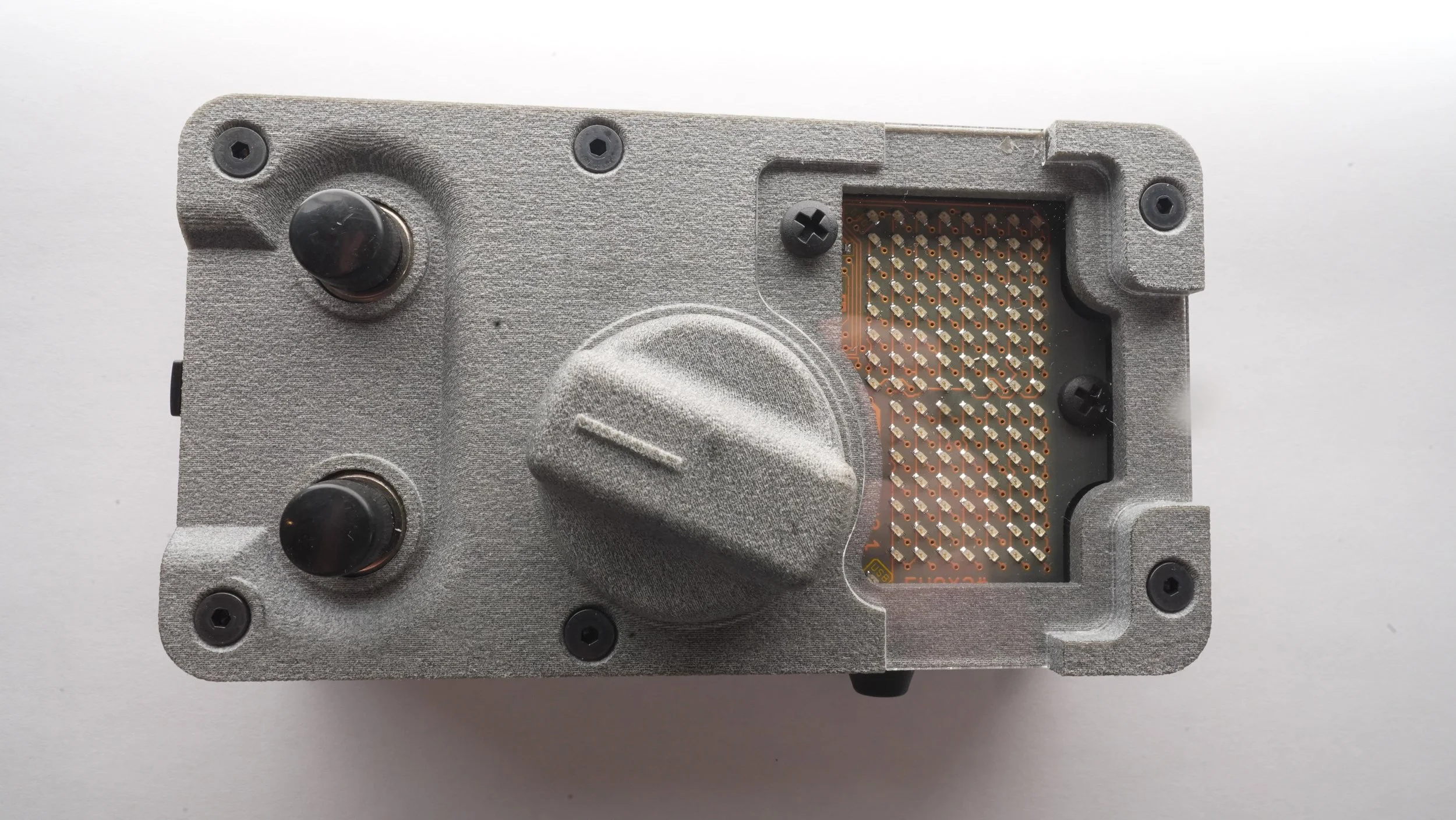
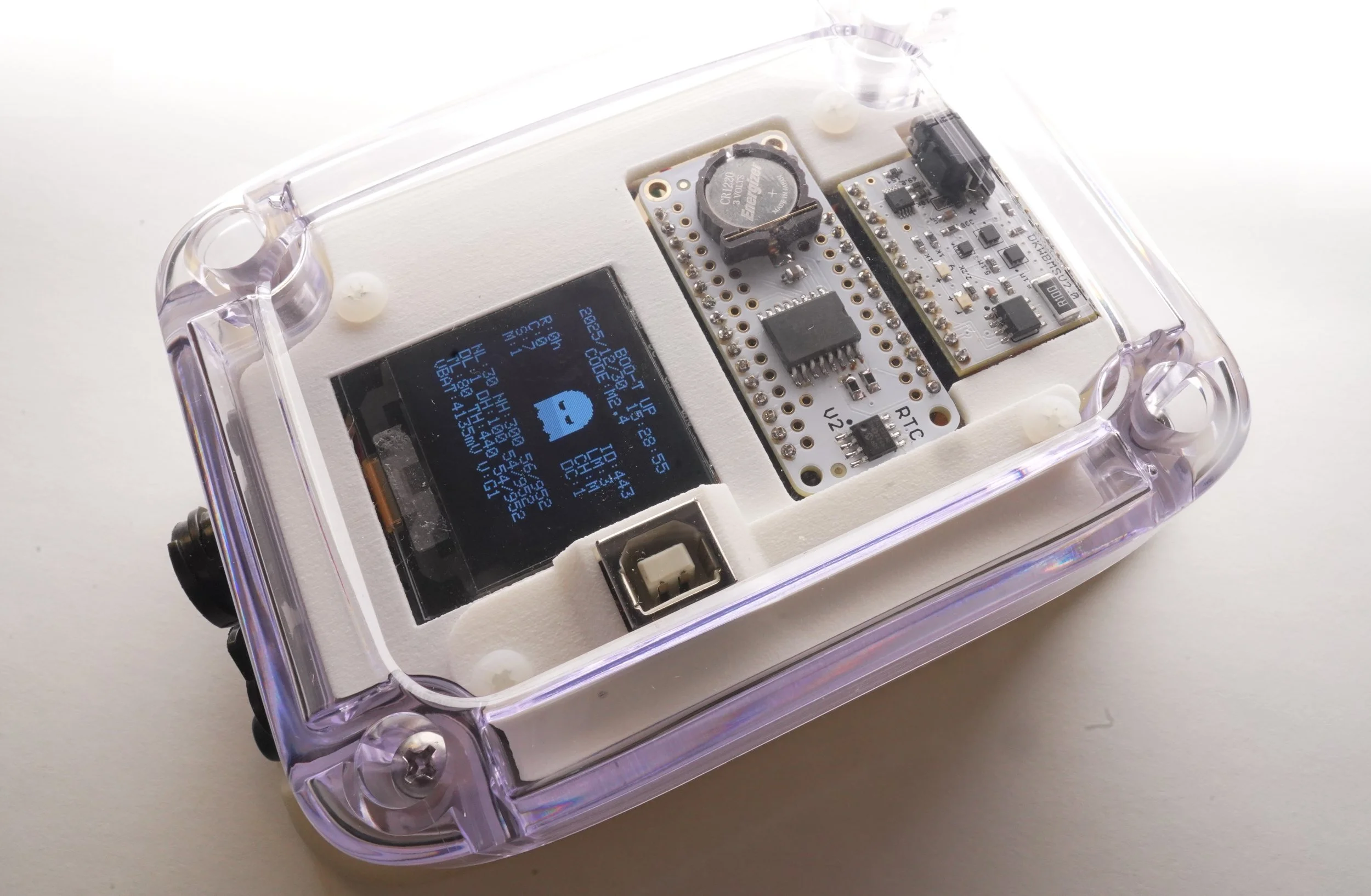
Note: Pictures displaying hand remote in transparent plastic, UTR-8100, is in-house prototyping only. Production is PA12-HP Nylon in Natural Gray)
The Ghost line introduces three main features that represent this leap forward.
1. UF2 Flashing for Code Updates: This enables bi-yearly updates for future hardware/signal advancements. You will be able to update the firmware yourself by connecting the remote set to a computer, where it will appear as a drive, and simply dragging the files over to complete the code transfer in seconds. The files will be available through downloadable content on the website.
2. Plant Setup Modular Expansion Slot: This feature allows you to add functionality by inserting swappable modules. The first included module is the Real Time Clock V2.
3. Hand Remote will have replaceable ~1/8” thick screen protectors sold in packs of 10. Available in both clear and orange.
Season One is called Spectre, and it will focus on tweaking and improving the code where a update will be available half way through the year to adopt all the changes and improvements we make together.
Looking forward to sharing more details about the G1 and the Ghost line soon.
See more developmental pictures below.
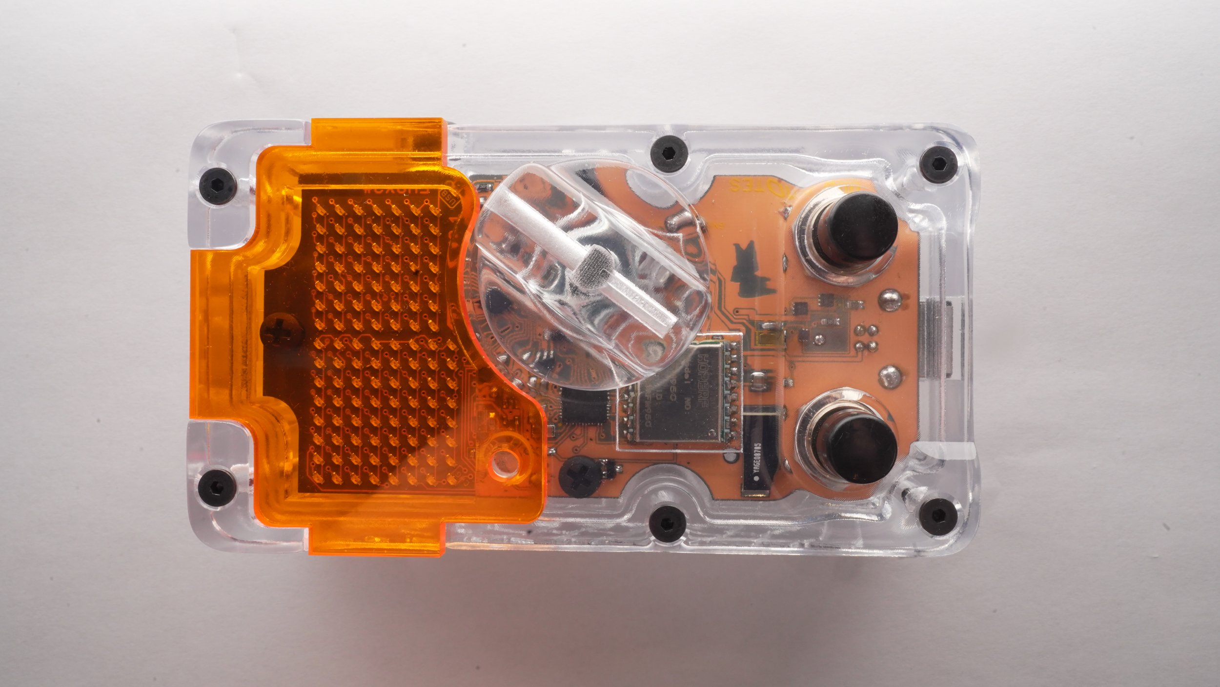
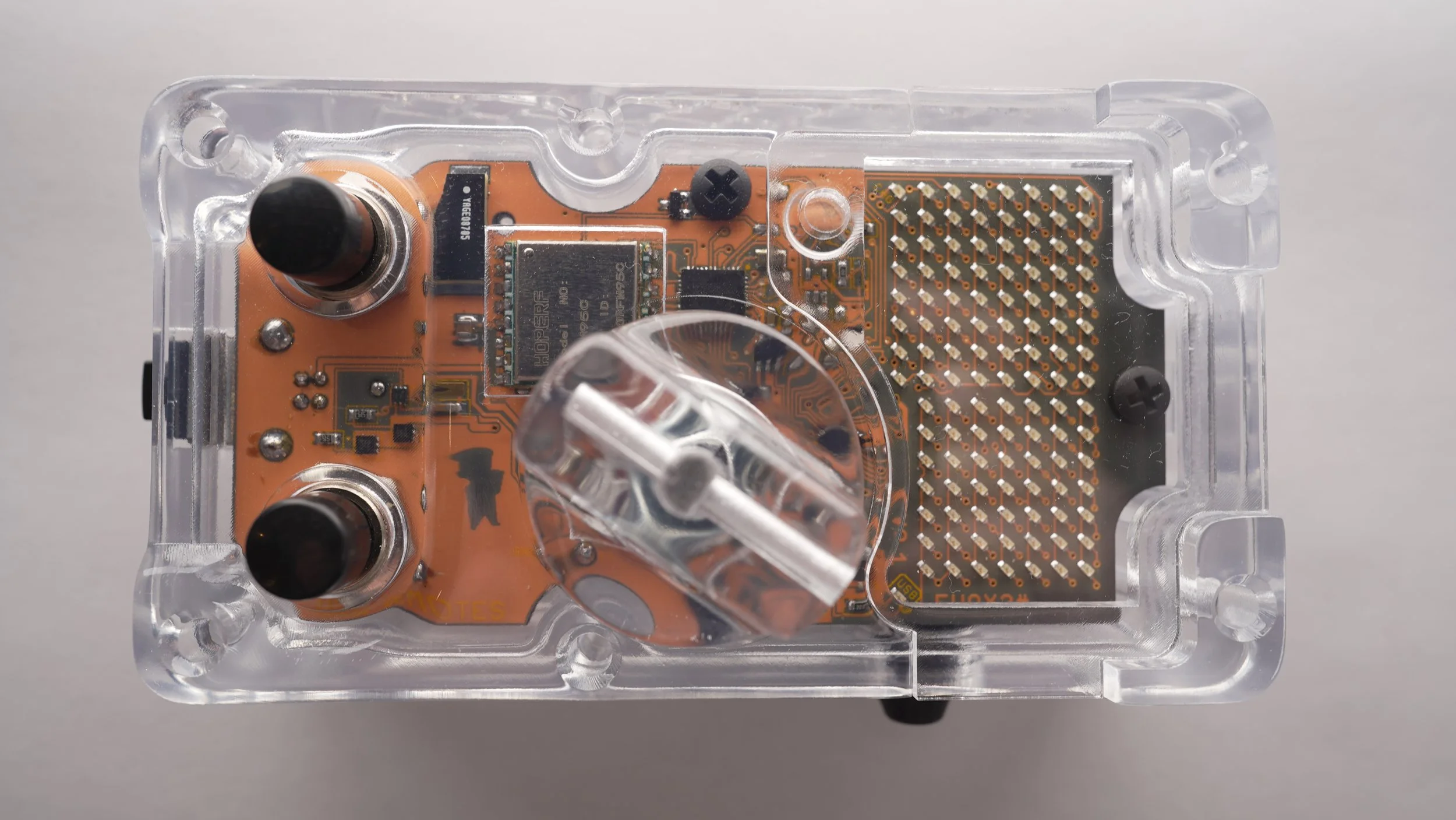
The new Ghost Line has this G1 model to take over plant duties. Now features a 128x128 OLED screen for metrics. Most important, it now has a user accesable data port to upload code when updates should become available.
I installed a Rheox on a 300D today. Let me tell you how I did it.

So first off, this is a canadian install with a third party plug. Namely the L21-20P which has five prongs. So the first step was to identify the function of his five prongs. This time, I decided to do all my multimeter measuring with the machine off. And it worked great!
I tried to approach the measuring as if I was you.lf. If you have a multimeter you can do it too.
I attached an exposed L21-20P plug into his receptacle to measure
I attached a exposed 120 plug into his receptacle to measure
On my multimeter, I used the continuity check (buzzer) one lead on the 120VAC hot and found the Hot on his remote plug. It was G
Next I connected to the neutral of his 120 plug and found W and X. Turns out neutral connected to 120 ground. So 120 neutral and ground are W and X. Which, doesn’t matter because I am after the two remaining prongs: Y and Z // You see, the above was only to identify Y and Z as the remainder prongs for remote circuit.
Next, machine still off, I got continuity between his prong Y and the corner of his bridge rectifier responsible for negative DC. Kitty corner went to his shunt so I deducted this was negative dc.
Lastly, by identifying the blue shunt wire, disconnecting the .250 spade, putting the machine on remote, I got continuity from the blue wire and the Z prong.
That could be enough but I went one step further. We started the machine and I measured a positive 125 volts DC at positive Z and negative Y ensuring the remote receptacle switch is set to remote.

Summary: With a multimeter, the above described all the steps necessary to identify the wiring with the machine off, then one last step measuring a live voltage. Why do I measure the live voltage. To ensure its DC meaning it’s the correct circuit.
Did I mention I installed a flyback diode. Flyback diode protects my gear from reverse voltage spikes.
Alright, so here is the deal, I saw that his two wires, in this case blue and brown, the brown leads straight to the brigdge rectifier. That means, in this case, that is the positive wire that you hookup the black wire of the flyback diode. I worded it that way because the blue wire never goes to the bridge rectifer, rather the rheostats.
List of Tutorials
Ditigal Contactor Video Link: https://www.youtube.com/watch?v=agXWUb3kx9E
Amazon Plant Setup Video Link: https://youtu.be/nz3FvcCFBg8?si=pQsbvHnkhWDvtG0V
Calibration Video: https://www.youtube.com/watch?v=YgL1f5WYX0Y
Classic IIID/300D/SAE300/3+3 Flyback Diode Install and Points
Updated 2025-08-09 just to revise the wording. In this tutorial, we will describe how we are to install a flyback diode prior to the use of a wireless rheostat receiver.
The purpose of the flyback diode and its install is the following: It protects the receiver and your remote switch from inductive voltage spikes released from the shunts when the circuit interrupts. some newer machines have this prebuilt. But, we shouldn’t take this for granted so we are installing a redundant one. PLEASE READ CAREFULLY SO TO NOT INSTALL IT BACKWARDS
The uttermost important note is to never disconnect both wires at the same time. That way you wont mix them up or lose track.


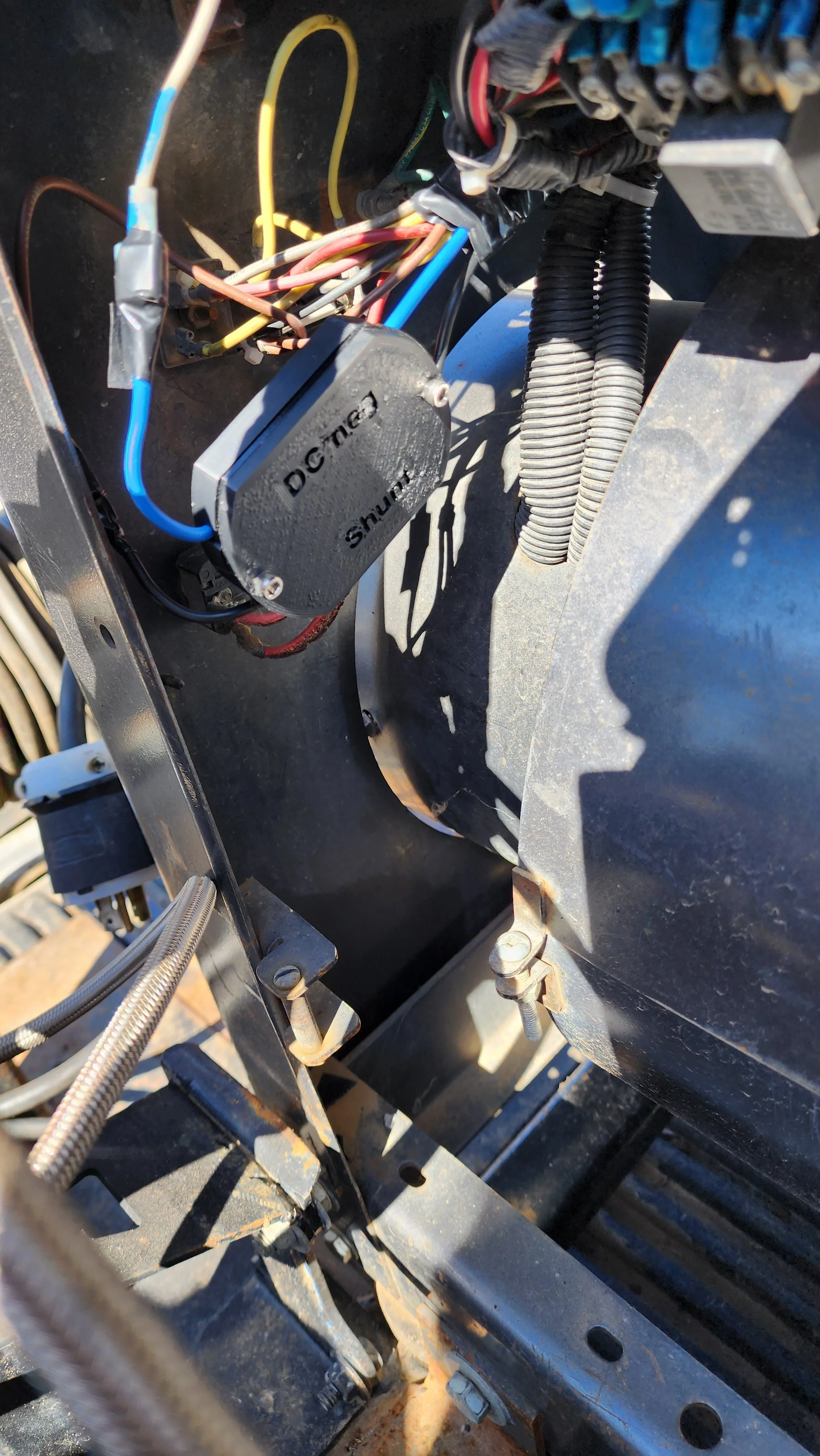
Step #1 Coming out of your generator are two 14 gauge wires which go into the back side of the J5 connector. As seen in the picture to the right, the J5 connector is the 4x3 connector consisting of twelve spots.
Step #2 The dkw remote flyback adapter provided in 2025 has two colors: black and blue. The black wire of the dkw remote flyback adapter connects to the spade that is connected to the wire that comes out of the middle row end spot on the back of the J5 connector.
Now for the other wire, for the sake of clarity, the dkw remote flyback adapter blue wire is connected to the spade on the wire on the outer row one in (pin3 in schematic)
You can see from the description above, the dkw black wire is always connected to a middle row pin and the dkw blue wire is always connected to a outer row pin.
Step #3 At this point, very recommended to try welding a bead with your original remote or machine rheostat. Why? Because if you installed it correctly, you will be able to still adjust your heat. If you installed it backwards, it may be stuck at min heat <- never tried it though
Flyback Diode Install Dummed Down
This section explains it in less words than dkwremotes.com/blog/flyback
Your goal is to install the flyback diode adapter inside your machine. It goes inline with the two wires coming out of the generator which have female and male spades.
The goal is to not install it backwards.
When you find the two wires coming out the generator, follow them to the spade connectors. This is where you will connect the flyback diode. If you keep following them, you will come to the back of the “4x3 connector”. Go the middle row. You see on the middle row, on the end, that is where one of your wires coming from the generator terminates. The black wire of the flyback diode connects to that one. Therefore, the blue wire on the adapter (marked dc neg) is the one that goes on the outer row one from the end.
Now that it is installed, your last step is to start the machine and try welding with the machine rheostat as per norm. If your machine runs a bead just like before, it is installed correctly.

Code Bug Fix (06-27-25) Starting receiver after the hand remote startup
While developing additional code for the receiver board, I came upon an inconsistency. If a receiver and hand remote are both in up5 down5 mode and the receiver is turned off. Then the hand remote is turned off and back on, then the receiver is turned on: The hand remote is in dial mode and the receiver is still in up5 down5 mode because it was saved to memory within the receiver
In this situation, the receiver light blinks but ignores the signal, and the hand remote shows dots only.
This is because traditionally, the receiver is turned on, then the hand remote is turned on sending the proper mode signal.
Code fix moving forward is Up5 Down5 mode is no longer saved to memory in the receiver. The receiver will start in dial mode, and should it receive a up5 signal, it will request the hand remote tell it what the last amps were and return to last position. That way regardless of which was started first, they will synchronize.
This is a receiver only update in the form of code M1.8

Up5Dn5 Attachment
A quick writeup regarding the Up5Dn5 attachment until I make a more comprehensive one.
In order to activate your side attachment, ensure first that your hand remote dial and receiver are communicating effectively. Then, do the following
put your hand remote dial in the middle. As in not minimum or maximum.
press both buttons of the up5dn5 attachment at the same time and continue holding
then press the top button of the hand remote (that means your holding three buttons)
Done right it will it activate. At tha point, it sends the signal on the “let go”
Additionally, if operated at very close distance to the receiver, the receiver will accept the signal, but the hand remote may miss the return signal. Operation has still succeeded.
To get out of this mode, restart the hand remote
Tips on syncing a replacement hand remote (Update Dec. 3, 2024)
Now listen. when a person buys a replacement hand remote, or has a second hand remote out of functional circulation as in a backup, the Channel it is on as in the frequency can be incorrect. That is because your receiver and functional hand remote will self assign frequencies to better facilitate communication based on the needs of the site. See video below
Channel search is activated in the following way:
Ensure receiver is on.
Turn hand remote on without touching any buttons
Put the dial to the max position (all the way to the right)
The with the dial still all the way to the right, hold both the up5 and down5 buttons
No matter what (~10 seconds) keep holding the buttons till it says “Rev 2 search” then immediately let go the buttons before the scroll ends. Otherwise you will abort.
it will setup the receiver, then ping until the receiver communicates back, then when done it will display numbers.
If it finds it, your done and you see numbers. its a one time thing

Calibrating your remote set so the numbers match on the machine to the hand remote
First step is to ensure both units, the receiver and hand remote are both off and not running.
Turn on the receiver by either plugging it in, or pressing the on switch (depends which model you have) and letting it bootup (10 sec)
While holding the bottom button, turn on the hand remote with the dial in the middle and once you see any leds lit on the screen, you can let go of the button.
At this stage, rotate the dial to confirm you have numbers displayed on the hand remote.
IF so, sweep from max to min repeating until screen dims. What I mean is when you go to max, ensure you see the max number and vice versa.
It will say ‘set min value’
You rotate the dial until it shows 4. Then press the up button.
It will say ‘set max value’
You rotate the dial to min which should show 5. Then press the up button.
Done correctly, it will say “calibrate, normal, min calibrate:”
You enter the desired low calibration number, press the up button.
It will say “refine”, you repeat step #11.
It will say “max calibrate:”
You enter the desired high calibration number, press the up button.
It will say “refine”, you repeat step #14.
Done right, it will say “end calibration”

Parts List of Items you can purchase third party
USB Port Cover:
https://www.digikey.com/en/products/detail/w%C3%BCrth-elektronik/726141001/3124565?s=N4IgTCBcDaIOxgGwEYAsyAMHkgLoF8g
USB Cord
https://www.digikey.com/en/products/detail/qualtek/3021001-03/1531288
USB Charge Block
https://www.digikey.com/en/products/detail/qualtek/QFWC-05-05/9771105?s=N4IgTCBcDaIDoBcAEBFAYgdQMIFoAMArPgSALoC%2BQA

New Shipping Instructions Form (Sep. 4 2023)
This page will allow you to submit your information, and description of the equipment. Then, we will review the submitted form and email you the required mailing instructions. The next step of inspecting/repairing your under warranty equipment.
DAMAGE BY WATER CORROSION: If your unit is opened and inspected for operation and the cause for the inspection is corrosion by water, if the unit cannot be repaired economically, the unit will not be reassembled and be decommissioned.
LEADTIME ON REPAIR: The current reasonable expectation of repair leadtime is lengthy and if first come first served basis.
Hand Remote and Receiver Proper Operation
Hand Remote has several areas of potential water intrusion. The usb charging port and dial potentiometer shaft. The hand remote is too be kept dry and not exposed to rain or rain conditions.
The receiver has several areas of potential water instrusion. Those are the quick connect ports at the bottom of the receiver and the breather gland. The receiver orientation is the same as all my receivers, cables pointed downward. This way the breather gland is on the side. And other mounting angle will render the breather or charging port susceptible to water intrusion by way of gravity. Mounting the receiver in the proper orientation makes it water resistant to normal weather conditions.

Retrofit - Adding a switch to a "looped" Miller 14 Pin

Should you have a Miller 14 Pin connector which has a wire loop already connecting pins A and B, this tutorial will give you the knowledge and parts to add a switch. A switch may be added if you come up to a newly designed machine such as a CST282 which requires you to toggle off the contactor, then back on, in order to weld. In the picture to the right are four parts in total. A push button switch, a boot for the switch, and two inline connectors
The links to purchase these three individual parts are the following:
https://www.digikey.com/en/products/detail/judco-manufacturing-inc/19-1088-01/63952
With the three links above, make note you need two 3M inline connectors, I will allow you to modify your looped miller adapter to give it a on/off switch. Do not strip the insulation off the wires
Step #1 is to cut the leads of the switch to 1.5” long each.
Step #2 is to cut the loop in half at a spot equaling the length of both looped, now individual leads.
Step #3 is insert one loop lead into the 3M connector and a switch lead, once both fully inserted, fully depress (I used pliers) the 3M connector. Refer to video
Step #4 Repeat step #5.


Repeater Tutorial
Ok, here we go. If you see the entire picture you will get it. This is a tutorial on signal repeating. The intent of repeating a signal is in instances where you may not get a great signal. here are a few examples:
welding machine in the way
building wall
trench (earth)
distance
receiver not in a good location on welder
If you own a second hand remote, you have the ability to signal repeat. It will instantly double your range or go around a corner. Here is how you do it:
Do not deviate from my instructions
Ensure your receiver, welding machine, and hand remote are on and functioning properly. (only one hand remote)
Turn off your handheld remote. and restart it holding the hostart button down or if an arcade remote hold the green down. Once on, you can let go the button (if the remote doesn't have a hotstart button, just proceed)
Then, enter the amperage adjustment menu (don't know how?, sweep the dial from min to max back to min until you see "amp constrain")
Enter 1 for min, Enter 2 for max
Done right, it will say "REPEATER ENABLED" go to step 11
If it says "DISABLED" go to step 8
Repeater function needs to be switched on
Enter the amperage adjustment menu
Enter 390 for min, Enter 395 for max. This will toggle by saying "REPEATER ON" or "REPEATER OFF" Go back to step#1
Now the hand remote will send a signal to the receiver and they will "both" change.
Do not turn off your repeater hand remote. do not turn off your receiver.
You will only be able to control amps with a second hand remote now.
Put your repeater hand remote in the middle somewhere higher off the ground the better
The repeater remote will show three bars, incoming signal strength, battery power, and outgoing signal strength
Now point form info
now what is happening is the second hand remote will go to the first one, it will send the signal to the receiver. then the receiver does math, sends a signal to the repeater which relays it to the hand remote.
If you have a hand remote, repeater remote, and receiver network, the only one you can get away with shutting off or restarting is the end hand remote.
if you turn off your repeater hand remote, you will need to go restart the receiver to put it "back to normal"
if you turn off your receiver, and you want the repeating signal thing again, you will need to turn off both your hand remote"s" and go to step #2
put your repeater hand remote with a "as clear view of the receiver as possible"
big tip --> do not start sequence at step #2 with a bad signal. I just realized right now I should have coded that you can only do it with a half signal. its better the repeater and receiver "talk" to each other their plans then walk away from each other.
if you ever get messed up, just turn off all three and restart
eventually, you'll get the hang of it.

NES Controller Cheat Codes and Instructional Page

The first thing the unit does when it boots up is it goes straight into a Channel Search. It might as well do this because your hand remote and receiver may have jumped frequency while it was off. It will blink rapidly whilst doing this and stop blinking when complete.
This Unit when powered up disables UP5 and DOWN5 buttons for the first fifteen seconds to allow you to perform sub functions such as node swap, repeater mode, channel search and or clone mode. During these fifteen seconds, the LED will not blink until the fifteen seconds expire. A rate of double blink every five seconds is a Transmitter node. Once every five seconds for a hand remote node.
In order to put the unit to sleep, you hold the select button for five seconds. You can let go of the button once you see it rapidly blink. To get it back online, you depress both buttons A and B to which it will blink rapidly but a slower blink. Then, don’t forget it will not go into UP5 Down5 Mode until the fifteen seconds expire. Again, these fifteen seconds are for clone mode, repeater mode and node swap
Swap from hand remote to transmitter: Up, Left, Up, Left, Up, Left, Up, Left, B, A
Repeater: Holding Left (B, A, B, A, B, A) Up, Left, Up
Stinger mode double blinks once every five seconds
Hand remote blinks once every five seconds
Repeater Mode begins with escalated blinks then triple blinks every five seconds, plus lights on data transfer
Clone Mode blinks every half second


Plant Receiver Battery Charging
Here’s the layman scoop on the battery charging on the plant setup. I hear you. You don’t have the insight, and know how that i have. I mean, when i’m confused, i just look at the lines of code and use a voltmeter to really see what’s going on.
Let’s hope i can type out in a clear way in this tutorial a few things you can do to alleviate any questions or concerns that may come from charging the receiver.
Ok, scenario #1: You charged all night and through pinging the receiver, it still shows 0%. Don’t worry quite yet. That digital readout 0% is my 0% and its not actually dead. if it was dead, it wouldn’t tell you anything. It’s like a car gas tank. They tell you its zero but its not actually zero. So not having access to measure it with a voltmeter, you can do these steps:
Read the last note at the end of the tutorial then come back here
Step#1 ensure the hand remote and receiver are on showing number changes with dial movement. plug it in if you have to.
Step#2 you will go into the submenu (the one you go to do a calibrate) But instead of entering say 4 and 5 for calibration, you are to enter 122 and 369. 122 and 369 is called “Bat ADC”
Step#2 in the function Bat ADC, your receiver will be stuck in a endless loop sending out a raw adc bat value three times a second to the hand remote. This value is averaged out on the receiver side but suffice to say that number should creep up as charging continues.
Wanna see the math behind Step #2. Here it is:
Say you activate 122and369, the receiver will measure the battery value in the following way. say the battery is 3.75vdc. It will divide that by half because i can only shoot 3.33vdc into my microcontroller. So we have 1.875vdc. 1.875 is divided by the analog reference of recent versions of 2.490 = 0.753. 0.753 is multiplied by 1023 which is the level of precision i can measure a whole something. like 1023 slices of one pie. i get 0.753x1023 = 770. So, if your receiver has a analog revision of 2.490 and a battery of 3.75vdc, your hand remote readout will show 770. fun right
All i’m saying is if you have 770, you could come back one hour later and see an increase of number to indicate charging.
When your done with this type of test, just to be friendly to the code, turn off both and let it charge, or restart both to get back into normal function
Note: 122and369 is a debugging menu not normally used. I’m saying if you use it and leave it on, only away from work because it crowds the airwaves.

Clone Mode for EVOX & EVOR
This page describes what you do when you receive the clone mode.
Clone Mode gets your hand remote programmed to you receiver
1) ensure the receiver and hand remote are off
2) turn on the hand remote only
3) after the hand remote says clone mode “waiting”, wait 5 seconds then plug in the receiver
4) it will detect you personal id and store it in the hand remote. That is step 1 of 3
5) Step 2 will setup the receiver for step 3
6) Step 3 will scan the frequencies looking for a ping from the receiver
7) once identified, it will acknowledge it, reboot the hand remote, and communicate with the receiver
Will not have to do this again